

The S series helical gear and worm gear reducing motors have high flexibility in installation positions. However, to ensure that it meets your specific needs, you still need to determine some technical details. If not specified clearly, it will be supplied according to the standard position.
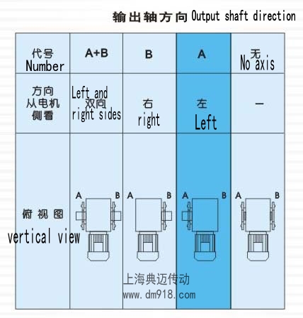
The directions of the output shaft are mainly divided into three types: A, B, and A+B. Meanwhile, for the flange direction, there are also options of A, B, and A+B for selection (for details, please refer to the legend table of the output shaft position). Among them, the A direction is set as the standard position.
This series of diverse output shaft and flange direction options are designed to provide you with more precise and demand-fitting configuration plans for your practical applications, to ensure that the reducing motor can operate stably and efficiently under various working conditions.