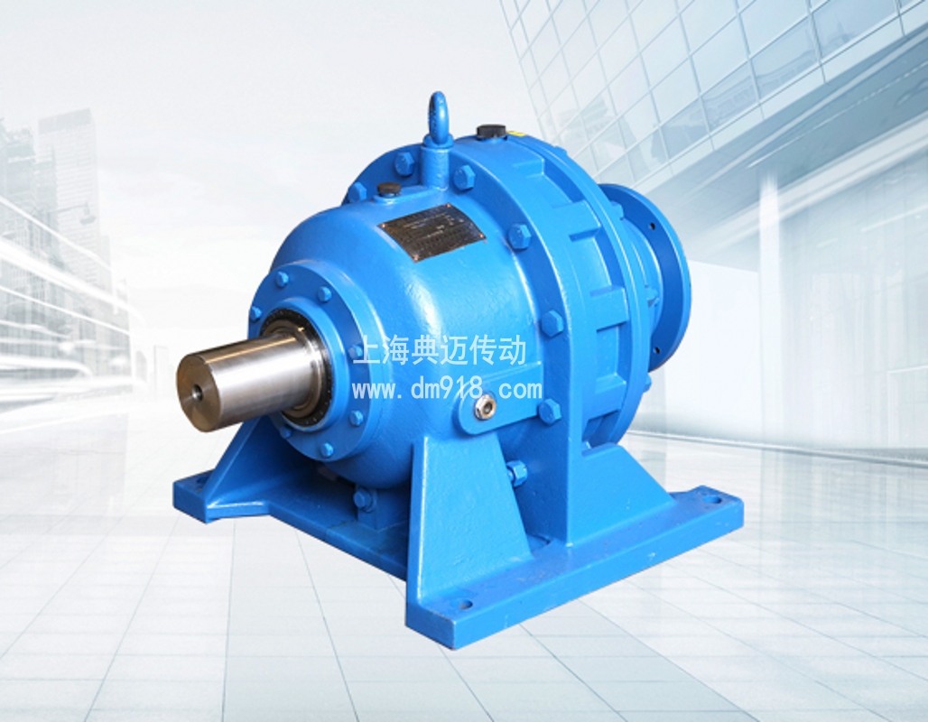
The entire transmission device of the “Cycloidal Pinwheel Reducer” can be divided into three main parts, namely the input part, the reduction part and the output part.
On the input shaft, there is a double eccentric sleeve with a 180° dislocation. On this eccentric sleeve, two roller bearings called swing arms are installed, thus constructing the H mechanism. The central holes of the two cycloidal wheels are exactly the raceways of the swing arm bearings on the eccentric sleeve. Moreover, the cycloidal wheels mesh with a set of annularly arranged pin teeth on the pin gear, thereby forming an internal meshing reduction structure with a tooth difference of one tooth. (It is worth mentioning that in reducers with a small speed ratio, in order to reduce friction, pin teeth sleeves will be equipped on the pin teeth.)
When the input shaft drives the eccentric sleeve to rotate for one cycle, in view of the unique nature of the tooth profile curve on the cycloidal wheel and its restraint by the pin teeth on the pin gear, the movement of the cycloidal wheel presents a planar motion form that has both revolution and rotation. When the input shaft rotates forward for one cycle, the eccentric sleeve also rotates for one cycle, while the cycloidal wheel rotates one tooth in the opposite direction to achieve the effect of deceleration. Then, with the help of the W output mechanism, the low-speed rotational motion of the cycloidal wheel is transmitted to the output shaft through the pin shaft, thereby obtaining a relatively low output speed.

